Dumbing down the Levoit LV-PUR131S Smart Air Purifier
The Levoit LV-PUR131S Smart Air Purifier is a HEPA filter (plus a carbon filter) with a particulate matter (PM) sensor and proprietary WiFi-based cloud connectivity. It’s a pretty reasonable air filter I use for my living room to help manage the indoor air quality. The replacement filters aren’t super expensive and the filter mostly just does its job… Until it doesn’t.
I’ve owned two of these units and both appear to have a flaw in their ability to handle AC power fluctuations. My first unit died about two years ago, but was just within the warranty period. To Levoit’s credit, they simply sent me a replacement unit that arrived very quickly and they didn’t want the broken unit returned to them. I enjoy a good teardown, so I got to work and found a pleasantly-engineered box. Nearly all the screws were the same type, the components were isolated in a way that were obviously optimized for assembly, and the “smart” bits of the unit were all semi-commodity hardware.
I found the following usable components:
- Espressif ESP-12F microcontroller as the brains of the unit (with WiFi connectivity)
- Cubic PM1003 particulate matter sensor
- Guangdong Welling brushless 24V DC motor with PWM controller
- A nice momentary roller switch
- A nice turbine
Aside from writing a library to connect to the Cubic PM1003 sensor, I added the components to my collection and didn’t think much of them for a couple years. Then I had a brownout and the replacement unit died the same death.
I contacted Levoit support, but their answer this time was that the unit was (well) beyond its 2-year warranty and there were no repair options offered. Unfortunately, I had recently stocked up on about a year’s worth of filters. I was already familiar with the guts of this unit, and I had a small Adafruit QT Py microcontroller I wanted to tinker with, so I decided to see what I could do.
Over the 4 total years of using this unit, I stopped using the “auto” fan control that used the PM sensor. I just left it on medium or high, depending on whether I’d cooked something smokey. The “VeSync” cloud integration was an annoying proprietary “smart home” app that was more advertizing than useful controller. Plus, there was no local-only option for use with HomeKit, so I didn’t mind giving this up. I really just wanted a button to pick a fan speed or turn the unit off. I didn’t even care about the capacitive touch panel on the top of the unit.
“On Schottky diodes”, or “How motors are also generators”
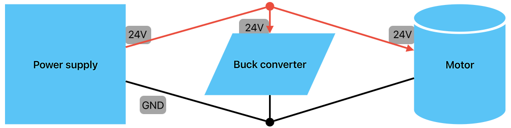
I knew that the fan motor required 24V DC and the QT Py microcontroller needed 5V, so I expected to use an inexpensive buck converter to step down the 24V source to 5V. This was the first time I was working with an inductive load in combination with a more sensitive electronic circuit, so I was only tangentially aware of terms like “flyback” and “backfeeding.”
I connected the motor and the buck converter to a power source, connected the motor’s PWM pin to V+ in order to instruct the motor to spin at top speed. Everything was powered and working as expected!
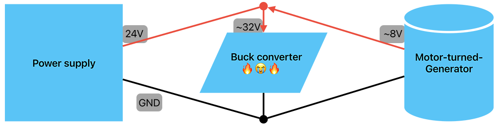
That is until I removed power from the PWM pin.
Since the motor’s spindle has inertia, as soon as the motor was no longer consuming electricity to turn the spindle, it acted as a generator feeding electricity into the same circuit. I assume that the motor probably wasn’t generating more than 24V of its own, but I did see my voltmeter top out around 32V total. Since the power source was still supplying its own 24V into the circuit, the motor added at least 8V for some fraction of a second. And since the buck converter was only rated for a max of 24V, it popped and released its magic smoke.
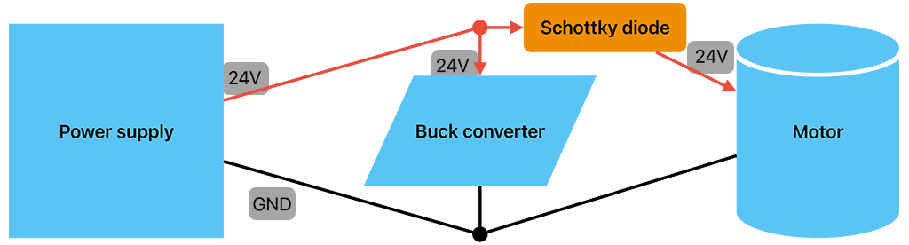
At first, I thought this might be flyback, which is a common electrical problem solved by putting a diode across the inductive load’s positive and negative terminals. However, the description didn’t quite fit and I actually think this was a case of proper backfeeding, which is solved by putting a diode between the power source and the inductive load. The other thing I learned is that some diodes are “slow” (act in milliseconds) and some are “fast” (act in nanoseconds). When I reset my circuit and tested with a “slow” 1N4007 diode to prevent backfeeding, I still saw a small, short increase on my voltmeter when the motor was spinning down. A Schottky diode is a “fast” diode that’s more typically used for this purpose and is far better at preventing backfeeding. Fortunately, I had exactly one 1N5817 on hand to use and it did exactly what I’d hoped for. (I did still keep a 1N4007 flyback diode in place out of superstition.)
Light CircuitPython development
I was glad to not get too bogged down in the programming for this project. The QT Py was designed to run CircuitPython and I only needed to control two pins, plus the on-board Neopixel, so this was a nice low-barrier way to move forward.
I needed to be able to detect when a switch was pressed and to set the duty cycle on a PWM output. The pinout diagram indicated that A0 would work as my GPIO for the button, and A2 was available for use as my PWM output. The code came together pretty easily. I have an infinite loop checking to see if the button’s state changed from the last iteration, and then I ratchet through an array of “fan speed” settings to control the duty cycle on the PWM output.
The code is available at thzinc/qtpy-fan-controller.
Power consumption and limiters
With a working microcontroller, I was able to hook it up to the air purifier with filters in place to measure power consumption. I ran the fan at 100% of its duty cycle and saw that it consumed about 1.5A and was moving far more air than the stock unit ever did on its OEM max speed. Since I’m expecting to use a Mean Well LRS-35-24 power supply that tops out at 1.5A continuous, I needed to set a lower limit in code. After a little tinkering, I settled on about two-thirds of the max duty cycle which feels about the same as the OEM’s max speed. At this duty cycle, the fan only consumes about 0.67A and has a healthy bit of headroom.
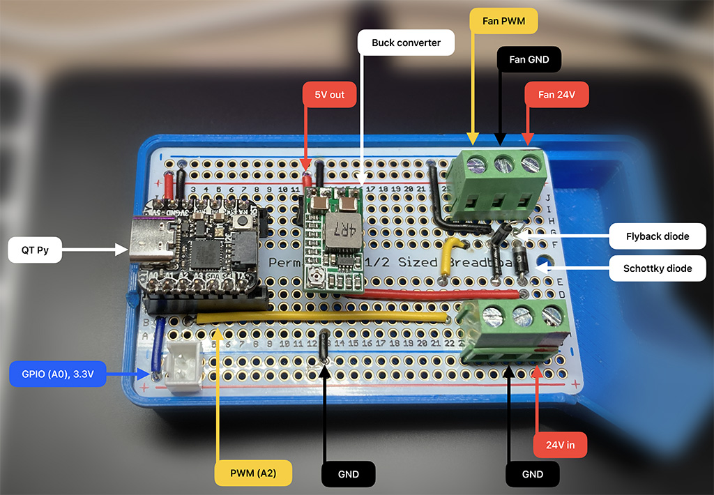
Circuit board layout
After breadboarding the circuit, I grabbed a perma-proto breadboard and spent some time carefully bending solid core wire to route power and signals around the board. In this layout, I tried to keep the motor’s power isolated from the “clean” power supply using the Schottky diode. I had some nice screw terminals that I salvaged from defunct relay assemblies to hook up the power supply IN and motor OUT lines, so installing or removing the board from the unit is easy and nondestructive. I also used headers to mount the microcontroller and buck converter to the board for when I eventually salvage them from this application.
Next steps
I’m waiting on a delivery of a new Mean Well LRS-35-24 AC-to-DC power converter that should comfortably fit inside the unit. There’s a switch in the unit that’s used to cut power when the filter panel is removed, so I’ll ensure that’s wired in appropriately, and then I’ll route cables around to find a home for the circuit board. I’ll pick out a switch from my collection of components and find a clever place to mount it to control the fan speed, and then I should have a much less “smart” but very functional air purifier!