Prototyping a volatile organic compound (VOC) and CO2 monitor on the Flipper Zero
I’ve been playing with environment sensors for a while to help me understand how factors of air quality correlate to my health. In 2019, I had a particularly bad asthma attack that was exacerbated by wildfires in California. Since then, I’ve learned a lot about how 2.5 micron particulate matter (a.k.a. PM2.5) in the air affects my asthma. I started correlating PM2.5 concentrations to my breathing and started wearing a respirator on poor air quality days. Then a pandemic of a virus that is primarily transmitted via 2.5 micron water droplets happened. In the time since the start of the pandemic, researchers have correlated good ventilation with reduced exposure to particulate matter that may transmit COVID-19. (Though the EPA, the CDC, and industry group ASHRAE warn that it’s only one factor in assessing risk of transmission.)
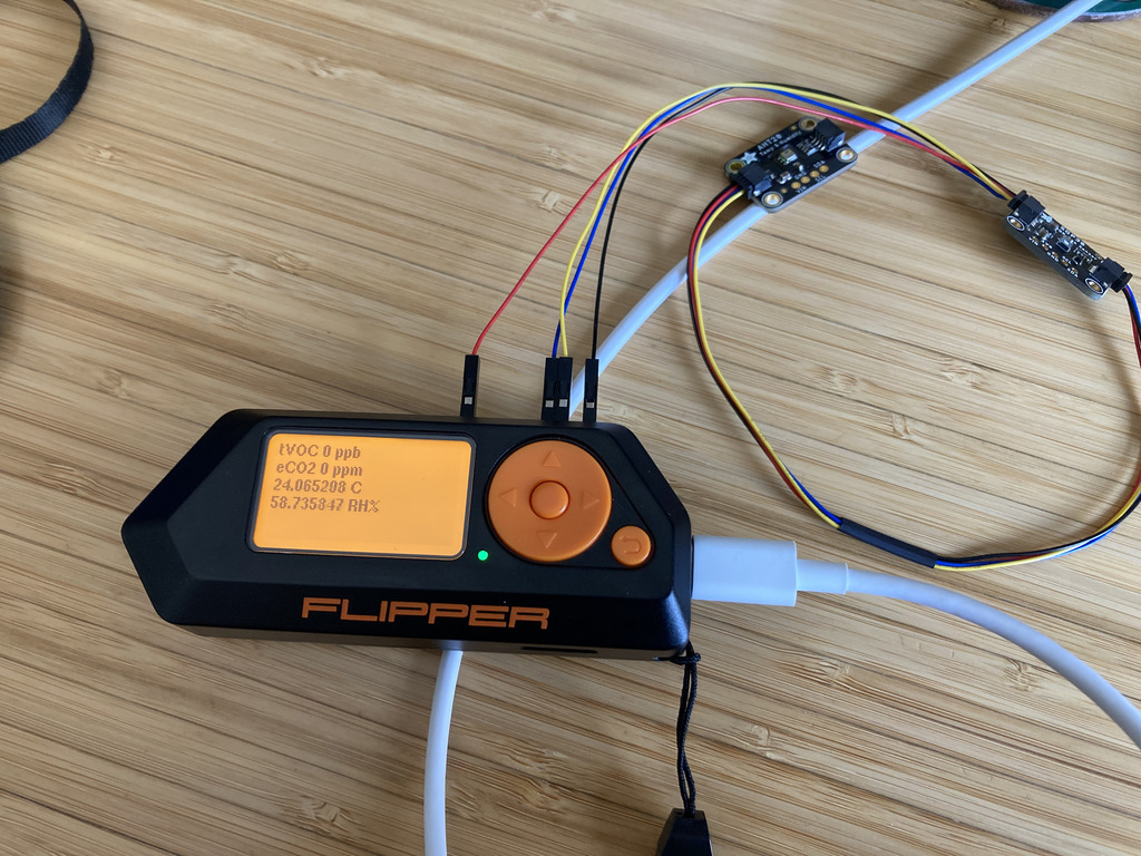
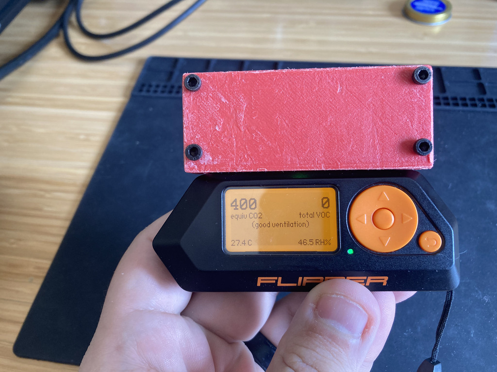
Separately, a fun group of folks launched a Kickstarter campaign for a small microcontroller with a several radios and I/O called Flipper Zero. After surviving “Chipageddon,” I received mine and started tinkering with it. I had a Sensiron SGP30 volatile organic compound sensor that also produces an “equivalent CO2” reading, so I decided to try making a wearable module for my Flipper to see if I could do it. If the idea proved feasible, I’d buy a “proper” CO2 sensor like the Sensiron SCD-30.
Getting started with C
Somehow, even though I’ve been programming since 1994 and working in software development for over 20 years, I haven’t actually worked on a “real” project in C before now. The Flipper’s firmware is entirely in C/C++, so that was my first hurdle to clear. Thankfully, the Flipper folks include a Docker build container, so getting a sane build environment was trivial. I was able to get started with atmanos’ flipper software docs, which was a really nice walkthrough of how to add an “application” to the Flipper firmware.
I quickly found that even though the firmware included a containerized build, using VSCode for C/C++ development still required my local environment to have specific tools and libraries configured. I didn’t really want to spend a lot of time focusing on tweaking my local setup, and I have been a semi-frequent user of devcontainer, so I spent just a tiny bit of time configuring devcontainer so I could launch VSCode within the context of the already-available build container. This–in conjunction with a few clutch plugins–made working in the repo really nice.
I knew I would need to learn the basics of showing stuff on the Flipper’s screen. Atmanos’ tutorial covered the basics of interacting with the GUI, and then I learned a bit more about fonts and canvas sizes from the clock app by RougeMaster. Then I needed a way to run a thread that communicated with my sensors that was independent of the main/GUI thread, so I looked at the Spectrum Analyzer by jolcese and learned about the furi_thread API.
Working with I2C peripherals
A popular means of communicating between integrated circuits (IC) and microcontrollers is I2C (formally, “I²C”). In some ways, it’s a bit like USB for ICs. (This is a tortured metaphor, I know.) The part of the I2C spec that is most common uses a 7-bit address to identify communication with a particular peripheral, and most peripherals either have a fixed address or support a few addresses that you can select from. For example, the Sensiron SGP30 has a fixed address of 0x58 (0b1011000).
As a part of the I2C spec, the 7-bit address is shifted to the left by one and the least-significant bit (LSB) indicates whether the controller intends to read (1) or write (0) to the peripheral. Some vendors choose to document their peripheral’s address as an 8-bit value with a “read address” and a “write address,” but this can be confusing when working with other vendors that communicate the I2C spec’s 7-bit address.
Both the Flipper’s furi_hal_i2c API and the underlying STM32 microcontroller use the 8-bit representation of an I2C address, which tripped me up for a day or so. I chose to represent my I2C addresses with a bitshift like #define SGP30_I2C_ADDRESS (0x58 << 1) in order to indicate the vendor-communicated 7-bit address but still ensure it’s usable by the API. It was helpful to see the other I2C drivers for LED drivers and power management ICs in the Flipper’s firmware.
One other aspect of communicating with I2C peripherals that caused me to stall for a bit was figuring out whether I needed to read and write using “registers.” (Texas Instruments’ Understanding the I2C Bus, page 6; uses archaic terminology for controller/peripheral) I don’t have experience with a broad range of I2C peripherals, so I hadn’t encountered a more advanced peripheral that supported the concept of registers. Ultimately, I was able to use the furi_hal_i2c_tx (transmit/write) and furi_hal_i2c_rx (receive/read) functions to just write and read bytes.
Making a hardware module
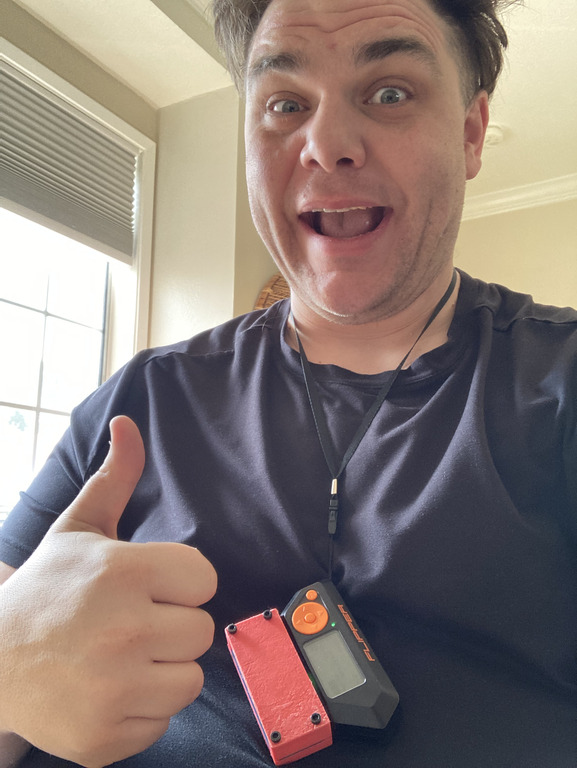
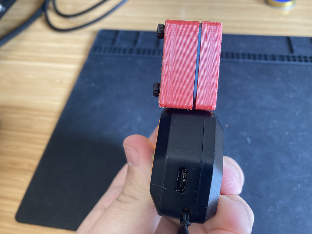
While I was working on the software, I had the sensors connected to the Flipper’s GPIO headers with some Dupont-style connectors. But my goal was to make this wearable by hanging around my neck, so I needed to make the connection a bit more durable.
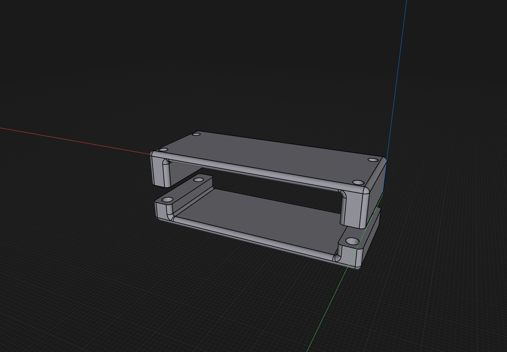
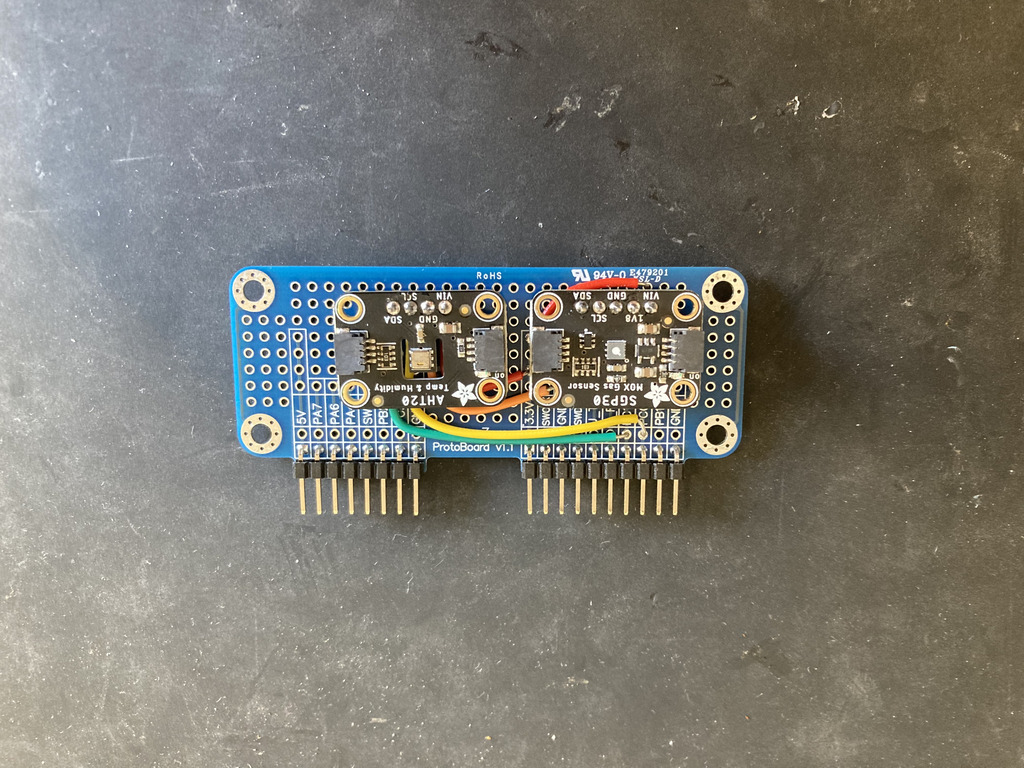
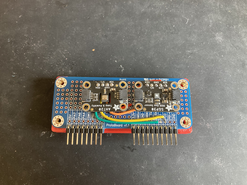
I bought a pack of prototype boards with my Flipper, so I had a convenient platform to which to affix my sensors and a simple case. I pulled my caliper out and measured the board, then got to modelling a simple case/cover in Shapr3D:
The actual connections on the board were pretty trivial. I just needed to connect the 3.3v, ground, clock (PC0), and data (PC1) lines to each of my two sensors. The two sensors I have are packaged with a STEMMA QT / Qwiic interface, so I had to do a little bit of clunky wire routing underneath the sensor breakout boards.
Once I printed the case, I installed the brass M3 heat set inserts and then screwed the case together with M3 bolts.
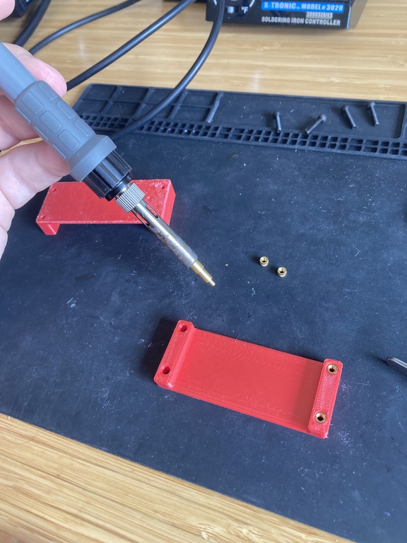
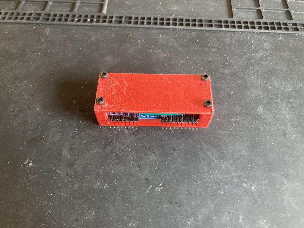
With the case around the prototype board, it feels pretty reasonably sturdy and I feel like wearing it on a lanyard isn’t adding much extra stress to the GPIO connector. I didn’t spend a ton of time on aesthetics of the case, but I’m pretty happy with the result.